
In the last part of our series on Roland's family of sound modules, we show you a number of ways that the more advanced synthesis parameters can breathe life into your patches.
XV and JV synths are proficient sound-design tools, capable of much more than simply playing back layered sample waveforms. So this month I'll examine some of the ways in which the basic sounds can be warped, mangled, filtered and otherwise manipulated to do your bidding. Let's ease into the lesson with a subject close to everyone's hearts...
Analogue Feel, The Simple Way
What defines 'analogue feel'? In certain quarters, the question itself can cause a debate lively enough to rival the Iraq conflict. OK, let's rephrase the question: what single aspect of analogue synthesizers is most often associated with 'analogue feel'? The answer would probably be 'pitch instability'. Analogue oscillators drift slowly over time, and in the case of analogue polysynths, there are also the subtle pitch differences between each voice generator to take into account.
You have probably already discovered the Analog Feel parameter in the Patch Common menu. It is intended to simulate drifting oscillators by adding gentle amounts of smooth, random pitch modulation to each Tone and to every voice played in a Patch, thereby thickening the sound. Values of up to 10 or 12 work well — but add too much and the sound begins to take on a rather drunk and disorderly character! The Analog Feel parameter is certainly a useful effect in its own right, and is very effective when applied to what I'd call 'composite' pads — string, brass or voice waves layered together, for example. However, it is only a stylistic representation — you could call it a caricature — of analogue oscillator drift.
This can be demonstrated with the following model of a two-oscillator analogue synth. Create or initialise a JV Patch consisting of two identical Tones. Assign to both Tones the same synth-type waveform — let's use Synth Saw 1, which is Tone number 26 in the INT-B group of the JV1080 and JV2080, or number 529 in the XV5080's INT wave group. Each Tone's filter should be wide open (or off) and the TVA envelopes a 'gate' or organ-like shape. There should be no effects, LFOs or pitch envelopes assigned, nor any detuning between the two Tones. With both Tones switched on, play a note — it will sound like a single, plain, unmodulated sawtooth wave. Even though there are two sawtooth waves sounding, they are literally identical — the same sample is used by both Tones, and they are playing as if phase-locked.
Now, go to the Patch Common menu, and add some Analog Feel. Just a tiny bit — say a value of four. You will hear the sound gently 'wiffling' around as the Tones' pitches are randomly modulated, and their wave cycles drift in and out of sync. Now take the value up to 20. The sound is much thicker now, with a lot more detuning. Crank it all the way up to 127, and the sound is now very out of tune. However, notice one thing: the speed of the random detuning cycle is the same at any value — only the depth is changed. 'So what's wrong with that?', you might say. Well, quite simply, it's way too fast. Analogue oscillators may well have instabilities, but not over such a short timescale. Not only that, but both Tones (our virtual oscillators) are being attributed with the same amount of instability. They need to be given their independence.
Simulating Analogue Instability
If you'd like to experiment with emulating 'analogue feel' in your own XV or JV synth, and would rather program the Patch from scratch, use an initialised Patch as a starting point and make the following parameter changes to create a model of a two-oscillator analogue synth with pitch instabilities:
| Parameter | Tone 1 | Tone 2 | Notes |
| WG Waveform | Synth Saw 1 | P5 Saw A | Try matching other analogue-type waves together, for example square, pulse, or triangle. |
| LFO 1 Waveform | Rnd | Rnd | |
| LFO 1 Key Sync | On | On | This allows each note its own independent LFO. If set to Off all notes would share the same pitch drift. |
| LFO 1 Rate | 8 | 6 | For maximum realism these can be set to their lowest value. |
| LFO 1 Pitch Depth | 1 | 2 | Any more than this and you'd send a real analogue synth to be repaired! |
| WG Random Pitch Depth | 1 | 1 | One of these Tones could be set to a value of two for a more exaggerated effect. |
| Fine Tune | 0 | 4 | The downloadable Patch is set like this, but it's down to personal taste. |
More Realistic Pitch Drift
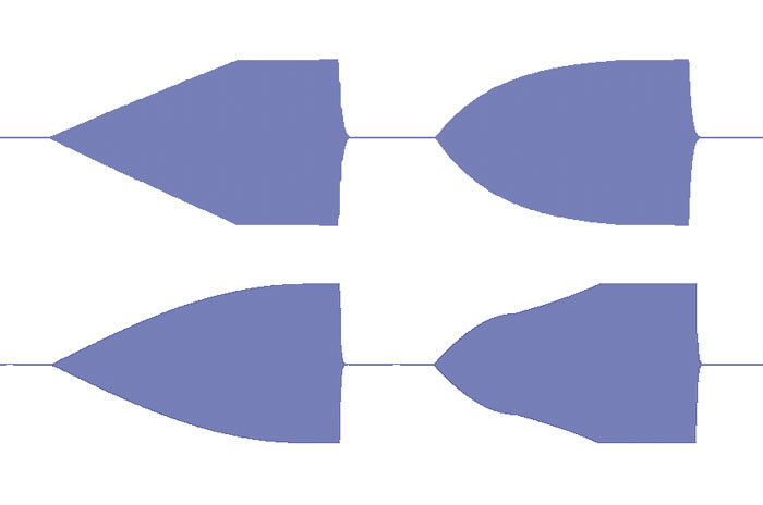
 Figure 1. A selection of sawtooth waves sampled from the JV2080 — it's easy to see that not all sawtooth waves look the same! The waves' origins are varied — Jupiter 8, Prophet 5 and D50 waves are represented.Let's try to get a bit closer to those 'idyllic' analogue instabilities. Starting with our basic double-sawtooth Patch, the first change to make is to one of the waveforms. At present our two Synth Saw 1 'oscillators' are identical in every respect, which is unlikely to be the case on a real analogue synth. Let's change the wave of one Tone to be a different sawtooth. The JVs provide several choices of sawtooth wave, which appear to sound the same — but in fact they are not. Figure 1 shows a selection of these waves sampled from the JV2080 — notice the variety of shapes, as well as the subtly different start points of the wave cycles. JP-8 Saw C might seem to be a good complement to Synth Saw 1, as its shape is distinctly different, its duty cycle starts earlier and its profile is the inverse of Synth Saw 1. Will these differences help to avoid phase cancellations occurring when the two waves are closely detuned?
In actual fact, pairing these particular two waves produces intense phase cancellations, owing to the inverted shape of JP-8 Saw C. Instead, the wave P5 Saw A is a much better sonic match — its downward ramp is slightly more linear than Synth Saw 1, yet it's very close in shape. Its duty cycle also starts earlier, and its amplitude is fractionally lower than Synth Saw 1. These are the sort of marginal differences between two real-world oscillators that might exist. And indeed, they exhibit minimal phase-cancellation effects when paired. However, pairing Synth Saw 1 with P5 Saw A on my XV5080 does produce phase cancellations. Against all expectations, Syn Saw 2inv actually works better than P5 Saw A on the XV, which only goes to show that even digital synths from the same stable have their differences!
 Setting up LFO 1 to produce slow 'analogue' oscillator drift.Next, we'll apply some random pitch modulation to each Tone to simulate oscillator drift. This is achieved with an LFO, using its Rnd waveform with Key Sync set to On, providing independent LFOs per voice. Pitch modulation depth should be as low as possible, ideally not more than ±2. Set the LFO rate to around eight or even lower. The effect produced is similar to that of the Analog Feel parameter, but at a very much slower rate that is a more reasonable approximation of oscillator drift. This technique has the added advantage that each Tone's modulation rate and depth can be set independently, further mimicking the inherent differences between two real-world oscillators. If one was to be a real stickler for realism, the random LFO rate should really be set as low as it can go (a value of one or two), but in order to have oscillator drift as a perceivable effect, a value of 8-10 falls within the acceptable realms of artistic license! If you are using an XV synth, you will see an additional Detune parameter on the LFO page, just below the LFO rate. This parameter randomly varies the basic LFO rate for each new note played, providing yet another element of instability — again, only a small amount is needed.
This in itself should be a good springboard template for creating a monophonic synth sound, but for polyphonic sounds there is yet more we can do. Analogue polysynths use discrete synth modules to generate each voice of polyphony. There are inevitably going to be pitch variations between the modules, and these can usually be heard when repeatedly playing one note. If the voice modules are dynamically allocated they will cycle around, and the variances in tuning become apparent — very much so if the synth is in dire need of servicing! This can be reproduced very simply (if crudely) on the JV synths by adding another type of random pitch variation. Not the smooth, modulating type that has just been discussed, but a randomly varying, fixed pitch offset that is applied with each new note played. This parameter, called Random Pitch Depth, is found by pressing the WG tab, then the Pitch tab. Only a tiny amount is needed — I'd recommend a maximum of +2. Finally, detune the 'oscillators' to taste using the Fine Tune parameter in the WG Pitch menu.
Smoother Attack Curves
 The slope characteristics of the JV's TVF and TVA envelopes can sometimes make it hard to create soft-attack pad sounds that articulate naturally. Sounds with a slow attack stage can feel slightly uncomfortable to play, and are perceived as lagging behind the music — especially if they have been quantised to the beat in a sequencer.
The diagram here shows four quite different attack envelopes. The top two were generated by Native Instruments' Kontakt, which thoughtfully allows you to vary the curve of each of its envelope stages to be linear, convex or concave.
Of the two, the convex shape on the right feels more natural to play, and does not seem to drag its heels as much as the linear shape on the left. It appears to start sooner than the linear envelope — yet it still retains a 'soft' quality.
 As you can see from the shape at the bottom left, the JV's attack slope begins in a predominantly linear fashion — becoming more convex towards the end of its rise time. It is that linear part of the slope that can cause slow attacks to sound sluggish.
Although the slope shape of XV/JV envelopes cannot be changed, the screenshot here shows a suggested setting to more closely approximate a convex curve — the results can be seen in the bottom right shape in the diagram. It's still a slightly odd shape, but pad sounds respond in a more natural way using this than with just a single attack stage.
Frequency Boost, Patch Structures & Serial Filters
 Figure 2. The Pkg filter — adding resonance boosts frequencies around the cutoff point. However, even at zero resonance settings there is still some boost.Dull waveforms can be given that extra bit of sizzle using the TVF's Pkg (peaking) filter type. Unlike the LPF, BPF or HPF, this filter type does not roll off frequencies above or below the cutoff point. Instead, it emphasises frequencies around the cutoff frequency — rather like a single-band parametric equaliser. The amount of gain is controlled by the Resonance parameter. The TVF Cutoff parameter is used to select the frequency you wish to boost — however, you can only boost, not cut. It is nevertheless a useful tool, and with high resonance settings the effect can be spectacularly aggressive. When used on sounds within a Rhythm Set, it's like having a whole rack of frequency boosters at your disposal, as each sound can have its own personal Pkg filter setting. I find it especially useful for adding sparkle to hi-hats, shakers and similar percussion. The downside is that those sounds lose their normal filter functions — which in the case of percussion sounds may not be considered too much of a handicap. Patches, however, can have the best of both worlds, by making use of different Patch Structures.
You can access the different Patch Structures by following the Common and Struct tabs within Patch mode, and they provide a variety of ways to enhance the basic waveforms of the JV and XV synths. Examine any of the factory presets, and the chances are that they will be using the default Structure, number one. This is the simplest Structure, placing the specified Tone pair in parallel, so that the Tones are not interacting in any way, and are treated as independent synth 'modules', having their own TVF and TVA. Each Tone pair can be assigned its own Structure, but for the purposes of these descriptions we will concentrate on just the first pair.
 The Structure page, showing separate Structures for each Tone pair. The Structure on the right is the one used for most of the factory patches, but that shouldn't stop you experimenting with the other options.Take a look at the screenshot (right), which shows the first Tone pair on the left using Structure two. Structure two breaks away from the 'one TVF/TVA per Tone' model, and combines the two TVFs in series. With this routing, the amplitude of Tone 1 is shaped by TVA 1, and is then combined with Tone 2, which is at full level. The Tone pair is then passed through TVF 1, then TVF 2, and finally the amplitude of the whole sound is shaped by TVA 2. This arrangement of serial filters means that we could have, for example, a downwards low-pass filter sweep on TVF 1, which is in turn operated upon by an upwards band-pass filter sweep on TVF 2. Referring back to the previous paragraph, TVF 2 could be of the Pkg type, enabling us to add some extra sizzle to the movements of the preceding filter (TVF 1) — hence the best of both worlds promised earlier.
Tips For Using Structures
To aid the adjustment of individual TVF and TVA settings when using any of Structures 2-10, turn off either one of the Tones in the pair. This re-routes the remaining Tone back to the basic 'waveform to TVF to TVA' Structure, and defeats the Boost or Ring Mod. This makes it easier to hear clearly how each of the TVF and TVA envelopes is evolving, and easier to audition waveforms — which may otherwise be difficult to distinguish when using Ring Mod Structures. Don't forget that Structures 2-8 use serial filters, so when you turn both Tones back on the filters will operate on both Tones equally, rather than on an individual basis.
If you wish to take advantage of the serial filters of Structures two, three and four, but applied to only one Tone, assign the waveform you wish to filter to Tone 2, and turn the level of Tone 1 to zero. As mentioned above, merely turning Tone 1 off will take the filters out of series, and you will be back to the basic Structure. Tone 1's level must therefore be reduced to zero, using TVA 1's editing page — note that Tone 1 must be selected to access this page. Also, remember that, since TVA 2 is the last stage in the Structure chain, it controls the final amplitude of the Tone pair, not just the level of one of the Tones.
You may have noticed that, in Structures 2-10, the Pan parameter of TVA 1 is disabled. This is because TVA 1 and TVA 2 are aligned in series, with TVA 1 always being before the two TVFs, so panning this TVA would clearly make no sense. TVA 2's Pan parameter still functions as normal, allowing the Structure's Tone pair to be panned differently to the other available Tone pair.
The Booster Structures
Structure three brings an interesting variation to Structure two, where a Booster is added between the two TVFs. For Booster, read 'Distortion', for that is its effect. There are four Booster settings: 0, +6, +12 or +18. The higher the setting, the more gain is applied to the signal emerging from TVF 1, dirtying it up before TVF 2. Structure four is similar, except that the Booster is applied just after the waves are combined, between TVA 1 and TVF 1.
 Here's how the Booster is incorporated into the signal flow of Structure three.The Booster has several very useful side-effects, and even a Booster setting of zero can cause a certain amount of distortion, depending on how much wave gain has been applied to the Tones. The most interesting thing is what happens to the sound in a general sense. The best description I can offer is that it seems as if the Tones' waveforms have been 'welded' together. They intermodulate in fascinating ways, producing additional harmonics not present in either Tone by itself.
For instance, taking our basic two-sawtooth Patch from earlier on, and detuning one Tone up a fifth, an additional sub-octave appears that was not previously there. Setting the Booster parameter to +6 or higher creates a very fat, rude sound that can form the basis of a powerful lead Patch. Experimenting with different tuning intervals produces results similar to ring modulation, especially striking when the pitch of one Tone is modulated with the Pitch Envelope.
The real fun comes when pairing off radically different waves — for instance, combining a sawtooth tuned up a fifth with the slow rotary organ wave (number 49 on the JV2080) and cranking the Booster parameter to +12 produces a very retro-sounding distorted Hammond, rather reminiscent of Dave Stewart in his Hatfield And The North days. Need the sound of Mellotron flutes salvaged from the wreck of the Titanic? Then try combining Monostrings C (INT-A 211) with Org Vox A (INT-A 252) at the highest Booster setting.
An additional benefit of using this form of Booster distortion is that the sound also works polyphonically. Each voice is distorted on an individual basis, and the effect is therefore totally dissimilar to using a standard global distortion effect, which reduces polyphonic playing to a horrible, unwieldy mush.
More Web Resources
This site is the home of Softvision's shareware XV / JV editor and librarian for PC.
Here you can find lots of free JV / XP Patches.
A useful XV / JV / XP resources site, including downloadable patches and links to a number of user sites.
A comprehensive XV / JV editor for PC, featuring nifty random patch-generation functions.
 The Patch editing window from Sound Tower's XVEdit XV/JV editing software.
The Ring Mod Structures
 Figure 3. Ring modulating the Sine 1 Tone with the much higher-frequency Sine 2 Tone produces the metallic, enharmonic Wave A. This is one of the ways you can create complex sounds from simple raw waveforms.Structures 5-10 are all devoted to ring modulation. In these, the frequencies of the two Tones are multiplied to produce new and complex enharmonic overtones, often very metallic in nature. This is rather like FM synthesis, but the crucial difference is that, unlike FM, neither Tone is designated as a carrier or a modulator. In fact, in the absence of any filtering, envelopes or pitch adjustment, swapping the waves of the two Tones produces exactly the same result. This would not be the case on an FM synth, where the Tone designated as the carrier forms the basis of what we hear, so a guitar waveform modulated by a sine wave would sound totally different to a sine wave modulated by a guitar wave.
Taking this comparison one step further, if you reduce the level of an FM modulator to zero, the carrier remains audible. Gradually increasing the level of the modulator will progressively alter the harmonic content of the carrier. Therefore, by applying an amplitude envelope to the modulator, an FM synth can generate complex timbral changes over time. In contrast to this, varying the amplitude of either Tone of a JV ring-modulated sound will merely change the overall level of the sound. We cannot vary the amount of modulation, because the amplitude ratio of the two Tones remains constant. So, on the face of it, the XV/JV implementation of ring modulation seems rather limited, as Yamaha DX7-style FM synthesis is not really possible.
However, the various Ring Mod Structures provide some workarounds that, although being a compromise, allow us to create some perfectly serviceable sounds using a very simplified form of FM. Let's say you want to give one of the Electric piano waves — D-50 EP A (INT-A 33) — a bit of DX7-style 'tine sparkle'. Take a look at Figure 4 below, which shows how to achieve this using Structure eight. Note that Tone 2 is allowed to bypass the ring modulator, as well as passing through it. This means that Tone 2 can always be heard (rather like the carrier in an FM synth) regardless of the activities of Tone 1. Tone 2 is therefore the logical place to put the basic electric piano waveform. To generate the 'tine sparkle', you can place a sine wave in Tone 1. The pitch of this sine wave determines the harmonics of the ring-modulated signal, so you need to turn it way up high to produce a bright, metallic sound — set its coarse tuning to +45 on Tone 1's pitch editing page. Also set Tone 1's pitch keyboard tracking to +50, reducing the range over which the Tone's pitch will track the keyboard.
 Figure 4. Creating a simple FM-like electric piano using Structure eight.
The sound now consists of the electric piano wave twinned with a constant high-frequency metallic timbre — the result of ring modulating the piano with the sine wave. Now we can use TVF 1 and TVA 1 to shape the sine wave, so that the metallic ring modulation decays to silence in a natural way. However, because Tone 1 is a sine wave, you'll find that reducing the cutoff frequency of TVF 1 sounds just the same as simply reducing its level, because the sine wave only has one harmonic to attenuate. So to make life easy turn off TVF 1 and use TVA 1 to do the amplitude shaping. You can also make TVA 1 sensitive to key velocity so that, the harder you play, the more 'tines' you hear.
Now all you have to do is to shape the timbre and amplitude of the final sound using TVF 2 and TVA 2. And there you have it — a simple but useable 'FM' piano. Note that, if you were to use a waveform more rich in harmonics than the sine wave, TVF 1's envelope could be used to change the cutoff frequency of Tone 1 over time prior to the ring modulator (so varying the resultant harmonic content of the ring-modulated waveform over time.) The cutoff frequency of TVF 1 can also be modulated by key velocity.
It goes without saying that the possible permutations of waveform, boost, ring modulation, detuning, envelopes and serial filters must run into the billions — so for that reason I recommend putting aside some quality time for getting to know these nine additional Structures. It's rather like discovering a synthesizer you never knew you had!
XV Low-pass Filter Types
The XV synths provide two additional filter types not found on the JV synths — LPF 2 and LPF 3. Whereas the normal LPF can be likened to a four-pole or 24dB/octave filter, LPF 2 and LPF 3 are more akin to two-pole or 12dB/octave filters. Although the Resonance parameter is disabled for both these filter types, LPF 2 appears to have a slight amount of wide-band emphasis around the cutoff frequency, giving it a more coloured sound than LPF 3 when modulated by a TVF envelope or LFO. Here are some suggested uses for each LPF type:
- LPF — the strong coloration and aggressive resonance make it the best choice for analogue synth impersonations, special effects and non-realistic timbres.
- LPF 2 — less coloured than the above, this can be used to good effect for natural instruments such as piano, guitars, and so forth. When swept by the TVF envelope, most of the timbral change occurs at the bottom end of the sweep, so TVF envelopes designed for the normal LPF will need to be re-shaped to work well with this filter.
- LPF 3 — A very neutral-sounding filter that works extremely well with any sound that imitates real-world instruments. TVF envelopes designed for LPF 3 also work well with the normal LPF, and vice-versa. It's particularly effective on drums and percussion, where the TVF cutoff frequency is modulated by key velocity — the results sound much less synthetic than with the normal LPF.
Using Breath Control
No matter how carefully a Patch's envelopes and filters are set, it is very difficult to achieve the sense of natural-sounding dynamics and articulation for every note that is essential for conveying a realistic performance. This is particularly true when emulating solo instruments such as flute, sax or brass. However, breath control really can, er... breathe life into XV and JV performances, whether you prefer to use a real breath controller or generate the same MIDI Continuous Controller value by waggling a slider or drawing curves into your sequencer. Happily, the XV and JV synths have all the tools you need to bring these sounds to life. All you need are a waveform, a TVA, a TVF, an LFO, and the modulation matrix. Creating such a Patch on a JV synth is most easily done starting from an initialised Patch. You can use as many or as few Tones as you like (for example a flute and a clarinet could play in unison), but for now just create a single-Tone Patch.
First, initialise a Patch — the Init tab can be found in the Patch mode's Utility page. Select Tone 1 for editing, then go to the WG Prm page and choose an appropriate waveform — we'll use Trumpet 1A (INT-A 187). Go to the TVF Prm page. Select the LPF filter, adjust the cutoff frequency to around 72. This sets the darkest timbre that you'll hear. Now set the Tone Level in the TVA page to zero, and then go to the LFO page and select the LFO 1 tab, choosing the sine waveform and setting a rate of 91.
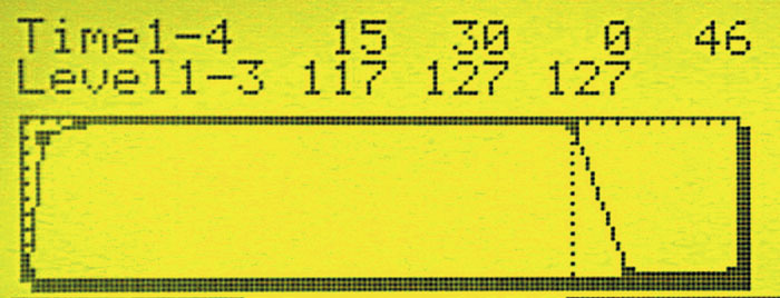
 Modulation matrix settings for breath control and vibrato.Go to the Control page, and set up the modulation matrix as in the screenshot (right). These settings control two things. The first line (Modulation) determines the vibrato characteristics as controlled by the MIDI Mod Wheel messages. Note that the amplitude modulation (AL1) is negative, unlike the pitch and TVF modulation. Strangely enough, this sounds more natural — it's a counterintuitive idea, but it works. Note too that the LFO rate is set to increase with greater deviations of the keyboard's mod wheel.
The second line of the modulation matrix (Breath) determines how the TVA and TVF will respond to incoming breath-control data. The value CUT:+16 and the TVF cutoff frequency are interdependent — it is set here so that the cutoff frequency begins to fall almost immediately after the breath controller's value drops below 127. Just to bring things full circle, go to the Patch Common page and add some Analog Feel. Wind and brass instruments present a perfect application for Analog Feel — in this case to simulate the fluctuations in pitch typical of a blown instrument. A value of around eight should do the trick.
And that's all there is to it. Don't panic if there is silence when you play the keyboard — that's as it should be. The TVA and TVF will not 'open up' until you send the JV some breath control data. If you have an assignable controller, assign MIDI Continuous Controller number two to a slider or knob, then try playing whilst moving the controller. You may also notice that key velocity has no effect on volume. As far as the TVA is concerned, this is an unavoidable aspect of the JV architecture — the TVA level must be zero for there to be silence when you are not 'blowing'. Since key velocities lower than 127 modulate the TVA level downwards from the set value, it's not possible to go lower than zero! Whilst this may seem like a bad thing, it's actually quite sensible. It means that both timbre and volume are under continuous control from your knob or slider, which means that they can be changed during the course of a note — something that is not possible with key velocity. It also means that every note can be articulated and phrased individually, something that is not possible with the TVA and TVF envelopes.
If you are using breath control on a sound that you intend to play polyphonically (for example, a four-part string accompaniment), then all notes within a chord will play at the same relative volume. If that's not what you want, why not assign the string sound to four different parts, each on its own MIDI channel, and sequence each part separately? That way you can articulate the violins independently from the violas and cellos, adding a huge amount of realism to the arrangement.