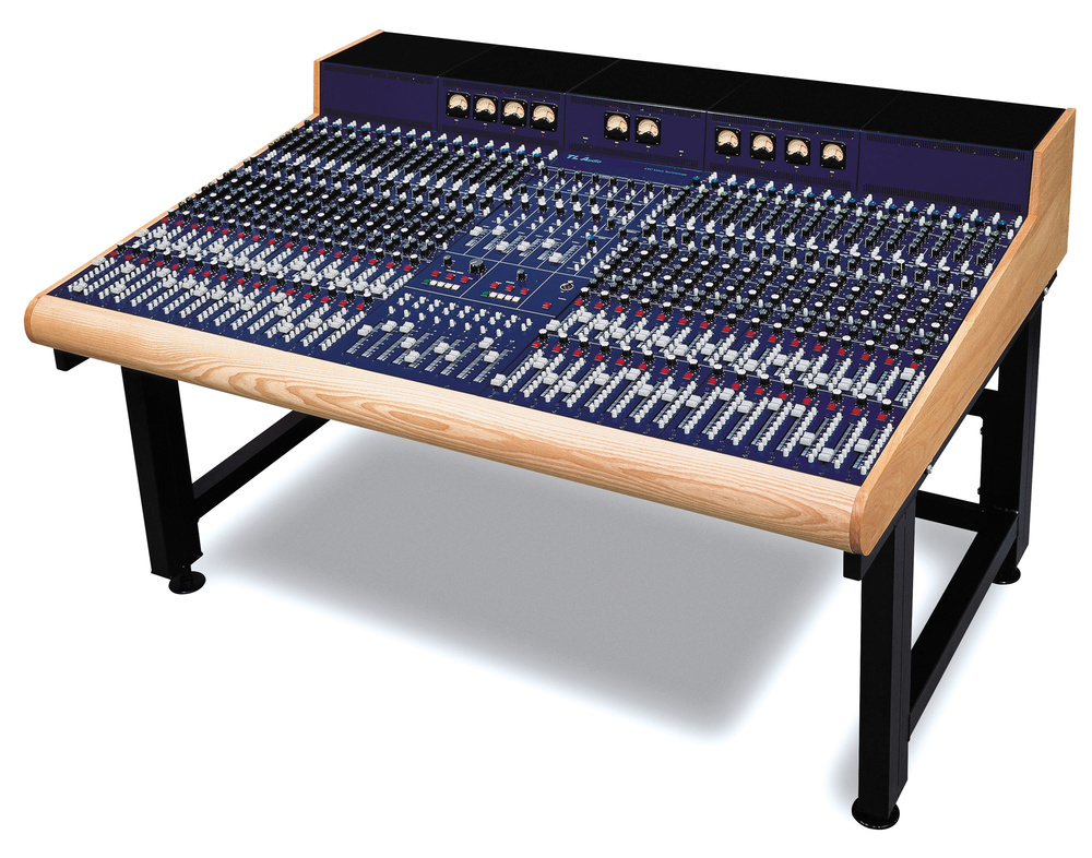
This unique hybrid eight‑bus mixing desk brings a welcome alternative to the established options.
In recent years it seems that the designers of mixing consoles, particularly for small and mid‑market products, have embraced digital technology almost to the exclusion of all else. Consequently, numerous ultra‑compact, assignable, and fully automated consoles are available, most of which are endowed with sophisticated onboard effects. Although these all‑singing and dancing consoles are powerful and empowering, there remains a significant demand for decent analogue desks, the best of which can still outperform any digital console in terms of audio specifications.
Advances in manufacturing techniques and the availability of very high‑quality, low‑cost components has allowed companies such as Mackie and Spirit (to name but two) to produce budget analogue consoles with technical specifications and sound quality to rival the very best of the high‑end analogue desks, which cost several orders of magnitude more. There is also a significant body of opinion which holds that most digital consoles lack the 'organic' sound quality of a good analogue signal path and that digital equalisation, whilst technically accurate, often fails to deliver the sonic goods.
Perhaps the widespread adoption of digital consoles is inevitable in the long term, but at present the shifting sands of 'digital standards' combined with the technical limitations of budget digital desks have to be considered, as does the remarkably low cost of high‑quality analogue consoles. Also, a lot of recording engineers have no need of total dynamic automation, wish to retain their classic outboard effects units, find assignable control surfaces slow and confusing to use, and actually prefer the sound of an analogue signal path!
TL Audio have developed their Valve Technology Console (VTC) specifically for these engineers. The desk may not appeal to everyone and certainly is not intended to compete head‑on with any of the digital desks in a straight 'bells and whistles' count but, for those who appreciate the design ethos of the VTC and the sonic qualities of vacuum tube amplification, this is an interesting alternative. As far as I am aware, there are no other commercially manufactured consoles currently available either with all‑valve or hybrid circuitry, so the VTC is unique.
Hybrid Technology
The circuitry of the VTC's signal path is largely derived from that employed in the highly successful TLA C1 compressor and its siblings. It is a hybrid design, using solid‑state electronics for the majority of the hard work (the well‑known SSM2017 chips are used at the front end, for example) with ECC83 double‑triode valve stages (on a 250V HT rail) placed in a number of critical locations. Each channel and tape return (monitor) path incorporates a valve within the input stage, and the eight group mix amps, the main stereo mix buffer and the Mix‑B (tape return or monitor path) mix buffer also enjoy valve stages.
Typically, each input source will pass through two valve stages (channel preamp and group) on its way to a recorder, and a further two or three (tape return preamp, Mix‑B master and/or main L&R master) on mixdown. By careful manipulation of the gain structure through the desk, it is possible to drive these stages harder or more gently to obtain various sonic characteristics. The valves are all located in the metering upstand at the rear of the console where adequate cooling can be assured to maximise life and reliability whilst leaving the control surface and solid‑state electronics comfortably cool.
The VTC is the work of ex‑Neve designer Dave Kempson and demonstrates his meticulous attention to detail. The 1.6mm glass‑fibre circuit boards carry high‑quality components, including 1‑percent tolerance resistors and overrated capacitors in the valve stages with gold‑plated ceramic valve bases. The mechanical design of the console is equally well specified, and the substantial steel chassis construction requires two strong people even to move a fully loaded 16‑channel frame! Additional eight‑channel subframes can be retrofitted in the field, and the fully modular channel strips are connected via a pair of multiway plugs and sockets on a rigid backplane. The wooden side cheeks and armrest are heavy American Oak, enhancing the distinctive vintage styling of the VTC.
As far as I am aware, there are no other commercially manufactured consoles currently available either with all‑valve or hybrid circuitry, so the VTC is unique.
The technical specifications are all pretty respectable in terms of noise and distortion, the latter increasing gently with signal level courtesy of the designed‑in valve non‑linearity. Frequency response extends up to 40kHz on all line and tape inputs and to 20kHz on mic inputs, with an equivalent input noise for the microphone amplifier quoted as ‑127dBu (at 60dB of gain and with a sensible 150Ω termination). All balanced outputs are capable of driving to +26dBu into sensible loads.
The desk itself is a simple eight‑bus, in‑line design with a central control and monitoring section and in‑line channels extending to either side. Channel sections are fitted in blocks of eight, the desk accommodating between 16 and 56 channels. The 16‑channel version measures less than a metre wide (975mm), while a 56‑channel console stretches to 2510mm side‑to‑side. The console measures 300mm high and 1180mm from front to back. An optional internal or external bantam patchbay is available and, although group and stereo master VU metering is built‑in, a separate (optional) LED bargraph display can be added to provide tape send/return metering on every channel. Third‑party fader and mute automation systems — either VCA or moving‑fader types — can also be installed.
An external linear power supply is provided, its capacity dependent on the chassis size (separate options are available for 16‑24, 32, and 40‑56 channel units). Each eight‑channel section within the console also has its own independent regulator section to ensure clean and stable power rails to the local circuitry. The audio mix buses running between the channel sections are all balanced to minimise interference and crosstalk, and to remove the problems associated with less‑than‑perfect ground references.
The Channel Strip
![]() Each channel is well equipped with equalisation and auxiliary sends, all inputs are electronically balanced and the operation is generally very clear and easy to fathom. I found using the VTC a great pleasure: not having to peer at an LCD panel and layered menu structure is a definite plus, and the 'WYSIWYG' culture of knob‑per‑function design still has an awful lot going for it in pure ergonomic terms.
Each channel is well equipped with equalisation and auxiliary sends, all inputs are electronically balanced and the operation is generally very clear and easy to fathom. I found using the VTC a great pleasure: not having to peer at an LCD panel and layered menu structure is a definite plus, and the 'WYSIWYG' culture of knob‑per‑function design still has an awful lot going for it in pure ergonomic terms.
Starting at the top of the strip, three small push buttons select phantom power, line input and a polarity‑reversal facility on the main channel input. The balanced line input is simply attenuated and impedance‑matched before being routed through the 'Line' and polarity buttons to the same amplifier that handles the microphone input. However, at minimum gain the line input can accommodate hot signals up to +30dBu — so handling full‑scale digital peaks from an ADAT or DTRS is not a problem! The input stage is very similar to that employed in TL Audio's own outboard preamp processors, so a high‑quality start to the signal path is guaranteed.
The red rotary gain control for the channel input (+16 to +60dB) is accompanied by a button to insert a 90Hz 12dB/octave high‑pass filter and a second button (labelled Flip) to swap the sources to the main input and tape return (Mix‑B) signal paths. The balanced tape return is switchable for +4dBu or ‑10dBV working and has its own green‑topped gain‑trim control (+/‑20dB). Both the main channel and Mix‑B signal paths contain valve stages (immediately after the Flip switch, in fact) and the channel path also has a pre‑EQ insert point. This is a conventional unbalanced implementation with send and return sharing a standard TRS jack socket.
There are eight auxiliary buses on the console. Aux 1 and 2 are derived post‑fader from the main channel path; Aux 3 and 4 can be switched (as a pair) pre‑fader, routed to Aux feed buses 5 and 6, or derived from the monitor (tape return) path instead of the channel. These four sends each have their own dark grey level‑control knob and independent On buttons, with three further push buttons for the Pre, 5+6 and Mix‑B switching associated with sends 3 and 4. Auxiliaries 7 and 8 are arranged as a stereo pair with a pan (blue) and stereo level (grey) controls as well as the same On, Pre and Mix‑B switching facilities as Aux 3 and 4.
![]() The equaliser is a comprehensive four‑band active solid‑state affair which may be inserted, in two sections, in either the channel or Mix‑B paths. The frequency extremes are catered for by shelving equalisers operating at turnovers of 80Hz for the LF and 12kHz for the HF, each equipped with a grey knob to adjust the boost or cut over a +/‑15dB range. Two overlapping parametric equalisers, covering the frequency ranges of 50Hz to 2kHz and 500Hz to 18kHz respectively, are provided for mid‑frequencies with boost and cut ranges of +/‑15dB. These are labelled LM and HM (low‑ and high‑mid), and the bandwidth of each is variable from 1.25 to 0.15 octaves, although the control is labelled Q and scaled equivalently between 0.8 and 7.
The equaliser is a comprehensive four‑band active solid‑state affair which may be inserted, in two sections, in either the channel or Mix‑B paths. The frequency extremes are catered for by shelving equalisers operating at turnovers of 80Hz for the LF and 12kHz for the HF, each equipped with a grey knob to adjust the boost or cut over a +/‑15dB range. Two overlapping parametric equalisers, covering the frequency ranges of 50Hz to 2kHz and 500Hz to 18kHz respectively, are provided for mid‑frequencies with boost and cut ranges of +/‑15dB. These are labelled LM and HM (low‑ and high‑mid), and the bandwidth of each is variable from 1.25 to 0.15 octaves, although the control is labelled Q and scaled equivalently between 0.8 and 7.
Either or both of the LF/HF and LM/HM sections can be inserted into the Mix‑B signal path by buttons alongside the Mix‑B fader (see below). However, as a consequence of this switching arrangement, the push button labelled 'EQ On' at the foot of the mid‑band equaliser section is a misnomer and could catch out the unwary. It appears that this switch only bypasses equaliser sections inserted in the channel path. The only way to bypass the equalisation in the Mix‑B path (to check whether EQ is having the required effect) is to switch the relevant section back into the channel path — which would have disastrous results if it were done while recording through the channel path with EQ! One of the normal advantages of the in‑line console design is that it is usually 'safe' to mess around with the Mix‑B (monitor path) without affecting the live recording to multitrack. Indeed, the in‑line structure traditionally makes it possible to start to build the final mix balance, equalisation and effects on the Mix‑B chain during live recording and overdubbing. This is not so on the VTC, and great care must be taken when experimenting with the equalisation in the Mix‑B path during simultaneous recording!
From the first listening session, the console's slightly warm, full, extended and open sound character was obvious. Much as might be expected, everything sounds big — but not in an exaggerated way...
The final two sections of the channel strip are the Mix‑B and main channel faders and their associated controls. The Mix‑B fader is a 60mm Alps unit with a large red Mute button and blue Pan control directly above. A pair of LEDs indicates the presence of signal and peak‑level conditions. Of the six push buttons alongside the fader, the uppermost activates the Solo mode. On channels and Mix‑B paths, soloing operates either as PFL or destructive Solo‑in‑Place according to the setting of the global 'Solo‑in‑Place' button in the Master section. There are no 'safe' buttons to prevent specific channels being muted in the latter mode, so returning effects through channels or Mix‑B paths in this mode is not advisable; fortunately, the VTC is well supplied with dedicated stereo effects returns.
The next two buttons, labelled 'Stat' and 'Auto', are provided for a third‑party fader automation system (Stat is intended to switch automation status on the channel whilst Auto will enable the automation). The Mix‑B bus is made available at dedicated outputs on the rear panel, but can also be monitored on the headphone outputs, Studio and Control Room loudspeakers, or can be routed in the main L&R stereo mix.
A button labelled 'Source' alongside the Mix‑B fader takes a post‑EQ, pre‑mute feed from the channel path and routes it through the Mix‑B path in place of its tape return, inserting it at a point just ahead of the Mix‑B equaliser position. This allows two independent mixes to be established simultaneously from a common set of sources — one on the channel faders and the other on the Mix‑B faders. The final two buttons in this section insert the LF‑HF and/or LM‑HM equalisers, borrowed from the channel path as already discussed.
The main channel fader at the bottom of the strip is a 100mm Alps type (although the console has been designed to accept P&G units as well as a third‑party motorised‑fader automation system if required). As with the Mix‑B fader, an illuminated red channel Mute push button and blue pan pot lie directly above the fader, together with signal present and peak LEDs (the Mute button also carries a channel identification number). The extended length of the channel fader allows nine push buttons to be ranged alongside, the first three providing identical functions to the monitor fader: Solo, Stat and Auto. The following five are associated with the output routing to the eight groups (in stereo pairs) and the master stereo mix bus (L&R). The sixth button (labelled bus) caused a certain amount of confusion initially, as it has nothing at all to do with channel‑to‑group routing. Instead, this button determines the signal feeding the channel's direct output (which would normally be connected to the corresponding track of a multitrack recorder). The default condition is for the channel post‑fader signal to be despatched to the direct output (via a balanced output buffer switchable for +4dBu or ‑10dBV working). Pressing the bus button replaces the channel post‑fader signal with an appropriate group output instead. The eight groups are allocated to channels in rotation such that Group 1 appears behind the bus buttons of channels 1, 9, 17 and 25, Group 2 on channels 2, 10, 18, and so on.
Master Section
The central master section is just as intuitive as the channel strips, with 12 clearly defined control areas. Across the top of the panel, just below the meters, are seven dark grey Aux master level controls for sends 1‑6 plus the stereo pair 7&8, each with solo and mute buttons (both with LEDs). Aux 7&8 is soloed in stereo and all auxiliary outputs are unbalanced. Directly below the Aux masters are six balanced stereo effects returns, switchable between +4 or ‑10 working. A blue‑topped balance‑control knob is accompanied by stereo solo and mute buttons, each with LED indicators, and a 60mm fader. At the top of the section, green rotary controls determine the level sent to a pair of dedicated headphone mix buses (see below), switchable to one or both.
 The VTC's master section. At the top are the master controls for the eight auxiliary sends, arranged as six mono and one stereo, with controls for the effects returns beneath. To the right are the Mix‑B master control and settings for the in‑built oscillator, talkback and dedicated headphone outputs. Below this are the main monitoring controls, with the master and group bus faders at the bottom.To the right of the effects returns section, three small subsections cater for the internal oscillator, Mix‑B master and talkback. The internal oscillator is a simple affair with a black rotary level control, an On button and a second push switch to select 1 or 10kHz outputs. The oscillator output feeds all group mix buses simultaneously, and can be routed to the channel direct/tape outputs by activating the bus buttons on each channel.
Talkback is equally simple, with a red‑topped rotary level control and four push buttons to preselect the talkback destination between Tape, Studio, Phones 1 or Phones 2. Again, a slight misnomer occurs here as the 'Tape' button actually routes the talkback signal to the group buses (which are not automatically routed to the tape sends at all). A second panel below and to the right is equipped with an XLR socket to accept a dynamic talkback mic and features an illuminated square button to activate the talkback (internally selectable for latching or momentary action). The control‑room monitoring is ducked in level when talkback is active to prevent howlrounds.
The Mix‑B master is tucked away between the oscillator and talkback panels, and features a dark grey rotary level control and a push button to route the Mix‑B output back into the main stereo mix bus. A valve stage is incorporated in the mix‑bus amplifier, and the dedicated rear‑panel outputs are electronically balanced.
The right‑hand side of the master panel carries a pair of dedicated headphone output sections, one directly above the other. Each is provided with a green master level control and push buttons to select and combine monitoring sources. An external input is available along with auxiliaries 3&4 and 7&8, Mix‑B, and the Control Room monitoring feed. LEDs indicate the current selection and a PFL button allows stereo monitoring of each Phones output.
The bottom of the centre panel contains eight 100mm group faders, each with three associated push buttons. The first provides PFL while the other two work together, routing the group output to the main stereo mix bus — the On button allocates odd‑numbered groups to the left bus and even groups to the right, whilst the second button enables each group to feed both L&R buses simultaneously, in mono. The ninth fader is the main L&R stereo mix‑bus master, which is accompanied by a pair of automation buttons labelled Stat and Auto. The groups and stereo mix‑bus amplifiers all include valve stages and unbalanced insert points. The main stereo mix output is offered on separately buffered balanced XLRs (at +4dB) and unbalanced quarter‑inch connectors (at ‑10dB).
Monitoring & Metering
The monitoring controls are located directly above the group faders, and are divided into Control and Studio subsections. Both have access to the same matrix of sources via large illuminated square push buttons, with the main L&R stereo mix, Mix‑B, two 2‑track returns and an external input all being available in any combination. Both 2‑tracks and the external input are balanced and individually switchable for +4dBu or ‑10dBV working. The Control Room section also provides switching for an alternative monitoring loudspeaker, mono, and to enable Solo (PFL) signals to override the main monitoring (complete with its own +/‑20dB level trim control). The button labelling refers to 'Solo Enable' whilst the knob is labelled 'PFL Trim', because the knob affects only the PFL level, not the Solo‑in‑Place level. The monitoring level is determined by a very obvious extra‑large dark grey knob — easy to spot and grab in a panic!
The studio monitoring has its own set of five source‑selection buttons together with a master level control and three further buttons. These enable the studio output, route the selected signal(s) to the Control Room monitoring, and force the selected sources to mirror the Control Room sources. All of the monitoring outputs are electronically balanced.
The built‑in metering consists of a set of 10 retro‑styled VU meters showing the group and main stereo mix‑bus signal levels. Each meter also has an associated red LED to indicate peak signals in excess of +18dBu (all balanced outputs are capable of +26dBu maximum, with +20dBu on the unbalanced outputs). An optional 'overbridge' provides 16‑segment bargraph metering of each channel, plus the L&R master with global switching to monitor either the tape sends or returns. The interfacing for this meterbridge takes the form of a 25‑way D‑Sub connector at the rear of each 8‑channel subframe.
In Use
Although the amount of time I spent with the review console was relatively short, its immaculate build quality and design integrity were immediately obvious, as was its outstanding usability. As with most knob‑per‑function console designs, operation was largely intuitive bar a few minor details (such as the function of the channel bus switches). As in‑line consoles go, the VTC was one of the easiest I have used, and certainly provides welcome flexibility in a conventional multitrack environment (whether analogue or digital, tape or hard‑disk based).
From the first listening session, the console's slightly warm, full, extended and open sound character was obvious. Much as might be expected, everything sounds big — but not in an exaggerated way — and by largely intuitive manipulation of the gain structure through the desk, individual valve stages can be driven harder or more gently to generate exactly the kind of sound quality required. The noise performance, perhaps, does not reach state‑of‑the‑art levels when compared to the very best solid‑state or even the latest digital desks, but is certainly nothing to be ashamed of and will not cause any problems in normal use.
The VTC is clearly not a budget eight‑bus desk — a look at the 'Prices' box below will quickly disabuse you of that notion — but, considering the nature of the construction, the hybrid circuitry, the sound quality and general performance, the asking price actually represents remarkable value for money. In further mitigation for a new installation, the cost of the desk can be offset against the negated requirement for a selection of outboard preamps — the VTC's front end is simply excellent and needs no external assistance at all. I should think the established major‑league console manufacturers will be having a few sleepless nights about the very significant challenge which the VTC introduces to this sector of their business!
VTC Console Connector Panel
 The VTC, as you would expect, features comprehensive interfacing: it's also available with a bantam patchbay as an option.
Each I/O module of the console boasts five connectors: one XLR and four quarter‑inch sockets (see picture above). The XLR accepts a microphone and is accompanied by TRS jack sockets for the channel line input and Mix‑B monitor input (tape return). A third TRS socket provides a channel direct/group bus output (tape send) and the last is an unbalanced channel insert point.
The central section of the console contains the remainder of the I/O, the majority utilising quarter‑inch sockets. The main console outputs include eight groups, eight (unbalanced) auxiliaries, Mix‑B Left and right, and the master stereo left and right outputs — these last on both unbalanced quarter‑inch and balanced XLRs. The six stereo effects returns occupy a further 12 TRS sockets, and 10 more provide unbalanced inserts for the groups and master stereo left and right outputs.
Monitoring is catered for with six TRS sockets for the two‑track and external monitoring inputs, and a further six for Control Room and studio speakers. Finally, two quarter‑inch sockets provide the headphone feeds. The external power supply interfaces via a large threaded connector at the bottom of the panel.
Prices
- 16‑channel £16,444
- 24‑channel £19,969
- 32‑channel £23,494
- 40‑channel £28,194
- 48‑channel £30,544
- 56‑channel £35,244
All prices include VAT.
Pros
- Superb sound quality.
- Flexible, ergonomic design.
- Integrity of electronic and mechanical construction.
- Unique visual styling.
Cons
- No EQ bypass for the Mix‑B path.
Summary
A novel eight‑bus in‑line mixing console that combines the best of valve and solid‑state technology in an easy to use, high‑performance package. Although not a budget console, the build quality and sonically rewarding character of the VTC easily justifies its cost.